|
This
is a preliminary procedure. I have not yet made a full-sized set of
blades from these drawings although I have made a set of ¼ scale
blades. Therefore the following procedure is not yet a proven technique.
- Just wanted you to know!
|
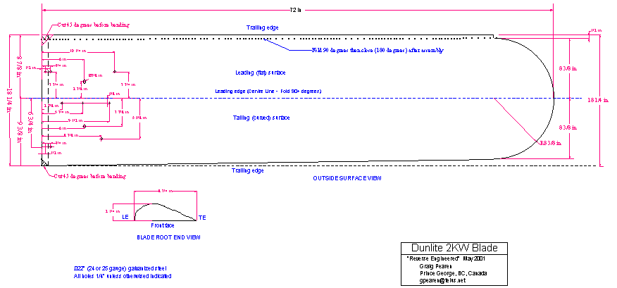
7-Make the 7/8” fold on the end of the blade blank. The fold should be to the outside of the blade. Bend it as far past 90° as your brake will bend it. Then carefully fold it down tight (180° bend) against the rest of the piece to form a double thickness of steel at the root end of the blade.When making this bend, use a hammer and work it a bit at a time so you don’t stretch the metal.
8-Mark, double-check, then centre punch all the holes.
9-Drill the holes using a wood block to back up the sheet steel so you get clean holes.
10-The drawing is of the outside of the blade so turn it over before making the next 2 bends.
11-Fold the ½”edge 90° or more. It will eventually be folded flat as described above.
12-Make the centre bend a little more than 90°
13-Lay the blade blank on a solid, flat surface with the open side facing you. The flat side is the narrower at the root of the blade than the curved side is.
14-Bend the now vertical piece to form a curved surface so that the two trailing edges meet with the piece that you are bending sitting against the base of the ½” vertical lip. You may wish to use the aluminium casting that goes inside the blade or a hand-carved wooden former to assist in getting the proper curvature. This should leave one flat surface and one curved surface. Clamp the two edges together in several places.
15-With a spot welder, weld the two edges together along the straight portion about ¾” from the edge. Space the welds about 4” apart.
16-Flatten the tip of the blade down tight and spot weld it in a few places but don’t weld the entire curve yet. If balancing is required, scraps of steel will be slipped into the blade at this point and all 3 layers welded at once.
17-Finish folding the ½” edge down tight making a 180° bend. Work slowly as described above so you don’t stretch the steel. This secures the trailing edge of the blade.
18-Spot-weld this fold also at about 4” intervals. Put extra spot welds at the ends or corners to make sure it is very secure. In the photographs, the small holes along the edges are all the places that I drilled out the spot welds on the original blade.
19-Using a similar procedure, make the blade stiffener and insert it into the blade.
20-If you are satisfied with blade one, make two more just like it. On the other hand, if you don’t like the results, chalk this one up to a learning experience, figure out where you went wrong, and try again. ?
